by Magnus Sjöberg
Given their potential to address issues related to limited petroleum reserves and accelerating global climate change, renewable fuels and improved engine efficiency are receiving significant research attention. Specifically, researchers are exploring the challenges of developing engines that can operate efficiently on alternative fuels, while offering high performance and low emissions.
At Sandia’s newly developed Alternative Fuels Direct-Injection Spark Ignition (DISI) Engine Lab, CRF researchers Magnus Sjöberg and Wei Zeng, together with Dave Reuss at the University of Michigan, are developing the fundamental understanding needed by industry to design and optimize engines for alternative fuels. The current focus is on flex-fuel engines that can run on pure gasoline or blends of gasoline and ethanol (up to E85, a fuel blend with 85% ethanol and 15% gasoline by volume).
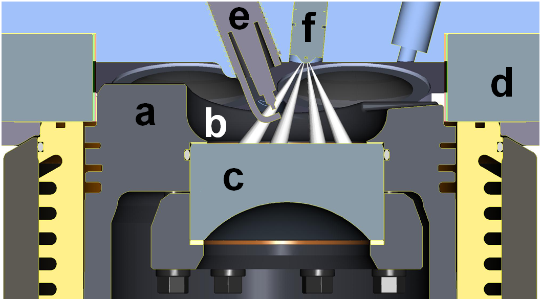
In the Alternative Fuels DISI Lab, this team is examining a spray-guided, stratified-charge combustion system—a spark-ignition (SI) lean-burn technology that achieves high thermal efficiency at low-to-medium loads by utilizing overall dilute combustion and minimal intake-air throttling. Typically, the flame speeds of ultra-lean mixtures are too low to allow stable spark-ignited operation. However, sufficiently high burn rates can be ensured by injecting the fuel late during the compression stroke and concentrating the fuel near the spark plug. As shown in Figure 1, a cross-section of the DISI engine within the lab, the centrally located injector and the piston bowl design help to stratify the fuel near the spark plug.
This said, stratified combustion presents two primary challenges:
- Precise and robust control of the fuel/air mixing is needed to ensure an ignitable and flammable mixture near the spark-plug gap at the time of ignition for every combustion cycle. This challenge is more intense for flex-fuel engines, as fuel properties change depending on the exact mix of gasoline and ethanol being used. E85 has a lower heating value than gasoline, as well as high oxygen (O2) content. Thus, engines operating on E85 require the injection of considerably more fuel mass for a given load (which in turn changes the stratification and mixing rates). High-ethanol fuels like E85 also cool the charge more during fuel vaporization and have different reaction chemistry.
- While maintaining high combustion stability, the engine must achieve low nitrogen oxide (NOx) and particulate matter (PM—also referred to as soot) emissions to avoid the need for expensive after-treatment technology.
Given these challenges, the research team is examining ways to capitalize on the different fuel properties to increase engine efficiency and performance, while achieving clean combustion. For this, a single-cylinder research engine is used for both performance testing and in-cylinder optical diagnostics. The team first conducted performance testing with an all-metal engine configuration over a range of operating conditions and alternative-fuel blends. They then examined the in-cylinder processes for critical operating points with high-speed optical diagnostics, including advanced laser-based techniques. As shown in Figure 1, two quartz windows provide optical access to the combustion chamber, allowing a side view and a wide-angle view from below.
![Figure 2. (a) NO/PM and (b) NO/combustion-instability trade-offs obtained by sweeping intake [O2] for various conditions at 1000 rpm. In the top graph (a), the green line shows that E85 with SOI = –6°CA can achieve research emissions targets for both NO and PM (delineated by the box in the bottom left corner outlined in gray). In the bottom graph (b), the green line indicates that E85 under the same SOI can also achieve superior combustion stability for low-NO operation.](https://www.sandia.gov/app/uploads/sites/248/2023/12/Figure-2.jpg)
Figure 2 shows key results from the team’s recent emissions and stability studies [1, 2] of gasoline and E85 using unthrottled high-efficiency stratified combustion. (For comparison, the red data points in Figure 2 show results for conventional well-mixed stoichiometric operation.) For these tests, the engine was fueled with one injection per combustion cycle using an 8-hole injector oriented to allow two of the fuel sprays to straddle the spark-plug gap.
Figure 2a charts nitric oxide (NO) and soot emissions for gasoline with start of injection (SOI) = –31 crank angle degrees (°CA, a typical SOI for stratified operation) and for E85 over a range of SOIs. As shown, at SOI = –31°CA, gasoline and E85 produce comparable magnitudes of NO and soot emissions—magnitudes that fail to meet research targets for engine-out emissions. The target emission levels are within the small box outlined in gray near the origin in Figure 2a.
However, it is possible to find operating points for E85 that achieve these emissions targets. The simultaneous low NO and soot emissions shown by the green data set in Figure 2a are achieved using a late SOI = –6°CA while reducing the load to indicated mean effective pressure (IMEPn) = 260 kPa (net over all four strokes).
Figure 2b shows the NO/instability trade-off for these conditions, as indicated by the standard deviation of IMEPn. For all conditions, NO emissions can be reduced by using exhaust-gas recirculation (EGR) to decrease the mole fraction of oxygen ([O2]) in the intake at the expense of combustion stability. For E85 with SOI = –6°CA, a very low NO level is achieved with only a modest reduction of [O2] in the intake.
Further, taken together, Figures 2a and 2b show that E85 with SOI = –6°CA achieves not only low NO and soot emissions, but also a superior NO/stability trade-off compared to all the other data sets. However, the general onset of elevated cyclic variability demonstrated in Figure 2b for all low-NO operation is an intriguing and challenging research area currently being pursued at Sandia with a number of high-speed optical diagnostics techniques, including particle image velocimetry (PIV) and planar laser-induced fluorescence (PLIF).

φ = Fuel/air equivalence ratio
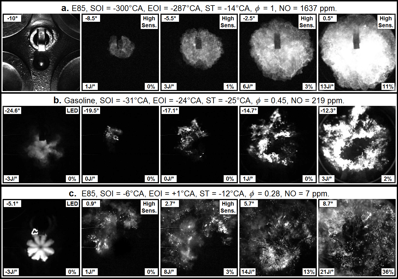
Figure 3—which shows results from high-speed imaging of broadband combustion luminosity collected via the wide-angle view provided by the piston-bowl window—illustrates the effect of different fuel types and stratification levels on the combustion mode. For orientation, the upper-left image in Figure 3 shows a well-illuminated view of the combustion chamber, with the injector tip below the spark plug and the four valves partially visible.
The top row, Case a, shows the flame spread for conventional well-mixed stoichiometric operation using E85. The turbulent flame develops in a nearly spherical fashion from the centrally located spark gap. The corresponding data points in Figure 2 are plotted as red circles. As can be seen, this conventional combustion mode is very stable and produces no soot, but emits a high level of NO. However, the high NO level for such conventional stoichiometric operation is not a problem because passenger cars normally have a three-way catalyst that reduces NO back to N2, facilitated by an exhaust stream that does not contain excess O2.
Figure 3 also includes images of two high-efficiency stratified-charge operating points: the middle row (Case b) for gasoline and the bottom row (Case c) for E85. The corresponding data points are annotated in Figure 2. (LED illumination for Mie-scattering of liquid fuel was applied for the left-most frames for Cases b and c, as indicated by “LED” in the upper right-hand corner of these frames.)
For these stratified operating points, very different spark timings (ST) were needed to minimize cyclic variations of IMEPN. For gasoline in Figure 3b, ST occurs near the end of injection (EOI), corresponding to the left-most frame. In contrast, for E85 in Figure 3c, ST occurs well before SOI. In this case, initiating the spark discharge before injection of the fuel is effective because the spark-plasma duration is roughly 1.5 ms.
Figure 3 shows strikingly different flame developments for these various combinations of SOIs, STs, and fuel types. For gasoline in Figure 3b, moderately corrugated flamelets develop from the spark gap and spread to medium radii in the piston bowl, forming a toroidal combustion region during the early part of the combustion process.
In contrast, for E85 in Figure 3c, the spark plasma first develops and is convected toward the left of the spark gap by the swirling in-cylinder gas flow. Once fuel injection starts, the head of the spray in the 11 o’clock direction quickly penetrates towards the spark plasma. The interaction of the spark plasma and the fuel jet disperses rich and weakly luminous flames over a wide area before main combustion event onset. As the heat release enters its main phase, the combustion luminosity increases simultaneously over large areas and the combustion appears very turbulent. Subsequent PIV measurements of the in-cylinder flow field have shown that the turbulence levels during and after combustion are higher for E85, which may be an important factor for the low NO emissions.
Current research on these and other aspects of stratified-charge engine combustion is focused on developing a broad understanding of these in-cylinder processes, with emphasis on cyclic variability and fuel-property effects. With a solid science base, the engine industry can better decide what combinations of fuels specifications and combustion technologies provide the most efficient engine, while best utilizing available alternative fuels and meeting stringent emissions standards.
References
1. Sjöberg, M. and D. L. Reuss, “High-Speed Imaging of Spray-guided DISI Engine Combustion with near-TDC Injection of E85 for Ultra-low NO and Soot,” Proceeding of the Combustion Institute, Volume 34, Issue 2, 2013, Pages 2933–2940. http://dx.doi.org/10.1016/j.proci.2012.05.033
2. Sjöberg, M. and D. L. Reuss, “NOX-Reduction by Injection-Timing Retard in a Stratified-Charge DISI Engine using Gasoline and E85,” SAE Int. J. Fuels Lubr. 5(3):1096-1113, 2012, doi:10.4271/2012-01-1643.