The CRF has a long and distinguished history of performing laser diagnostic measurements in turbulent flames and documenting the processed data and corresponding boundary conditions in an online database accessible to modelers.
Because of the desire for highly refined measurements of species concentrations and local temperature (using combined Rayleigh and Raman scattering), these measurements have always been performed in soot-free flames that allow for application of these laser diagnostic techniques.
However, some important combustion applications, notably traditional diesel engine combustion and aviation gas turbines, produce a considerable quantity of soot during the primary combustion phase, such that the amount of soot emitted in the exhaust creates a complicated interplay between the soot formation, turbulent mixing, and soot oxidation processes. Accurate predictions of soot emissions from these types of combustion systems require definitive datasets of experimental quantities in well-controlled flames for soot model development and validation.
Recently, Chris Shaddix and postdoctoral researcher Yao Zhang completed work on a project to develop such a database for the use of turbulent flame modelers. The work was supported by the Strategic Environmental Research and Development Program (SERDP), a Department of Defense research program that seeks solutions to environmental issues associated with U.S. military activities. In collaboration with other research program participants, Chris and Yao chose ethylene and a simple two-component surrogate consisting of n-dodecane and m-xylene for JP-8 (the standard U.S. military aviation fuel) as the two fuel systems to be researched. The first challenge of the project was to develop burner systems for these fuels that were amenable to both laser diagnostic measurements and turbulent flame modeling. Based on the
previous success of the “Sydney burner” for piloted, non-premixed jet flames fueled by diluted methane, this burner design formed the basis for the ethylene and JP-8 surrogate burners. A design drawing of the burner exit plane of one of the new burners is shown in Figure 1, together with a photograph of the ethylene burner. For the liquid JP-8 surrogate, a flash vaporization and heated fuel vapor delivery system was developed.

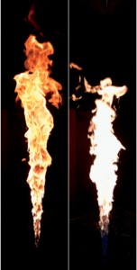
Photographs of the canonical ethylene and JP-8 surrogate flames that were used for most of the experimental measurements are shown in Figure 2. Joint planar imaging of polycyclic aromatic hydrocarbons (PAH) and soot was performed to provide an understanding of where soot nucleation occurs in these flames. Similarly, joint imaging of hydroxyl radical (OH•) and soot was performed to show where soot oxidation occurs. The ethylene flame imaging showed soot layers that were always surrounded by OH•, and indeed no soot emission from that flame was visible, whereas the JP-8 surrogate flame showed quenching of the OH• layers and occasional release of soot near the top of the flame, consistent with the observation of soot in the exhaust. Figure 3 shows an example of joint OH• and soot imaging.
Quantitative, time-resolved measurements performed in these flames include soot volume fraction (from laser-induced incandescence), local soot temperature-concentration statistics (from simultaneous laser extinction and two-color pyrometry measurements with a ceramic probe), and local radiant emission intensity (from a calibrated thermopile with an anodized light tube). One of the complications in deducing the soot volume fraction in a turbulent, sooty flow is the existence of “signal trapping” (i.e., the loss of signal by optical extinction as it traverses soot layers between the location of signal excitation and the optical detector, outside of the flame). To correct for signal trapping, laser extinction measurements were performed on a time-average basis across the full width of the flame for a sequence of radial positions and heights, and then the results were interpolated to yield a 2D signal trapping correction for the entire flames. Processing of the experimental data is still in progress; when completed, it will be posted onto the CRF website for access by turbulent flame modelers.
