Measurements of Thermal Stratification in an HCCI Engine
As automotive and diesel engine companies strive to find more fuel efficient, environmentally friendly technologies, some have turned their attention to Homogenous Charge Compression Ignition (HCCI). HCCI engines use fuel mixed with a substantial amount of excess air or recirculated exhaust gas that is compressed in the combustion chamber until it autoignites. The resulting combustion is a flameless and low-temperature burn that consumes less fuel than traditional spark-ignition internal combustion engines, and therefore, produces less carbon dioxide (CO2). The HCCI engine thus has the efficiency of a diesel engine but without the accompanying nitrogen oxide (NOx) and particulate emissions. However, many challenges remain before HCCI engines are available for consumer use. CRF researchers John Dec, Nicolas Dronniou, Wontae Hwang, and Magnus Sjöberg, along with collaborators from other institutions, are working toward a better understanding of those challenges and potential solutions.
Chemiluminescence
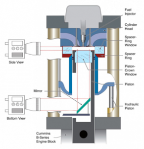
One of the main obstacles to HCCI development is that the maximum loads these engines can produce are below those of spark-ignition and diesel engines. At the higher loads desired, the pressure rise rate (PRR) becomes too high, eventually resulting in engine knock. The CRF team used chemiluminescence in an optically accessible engine to investigate the homogeneity of the charge (Figure 1).
The results show that even when the air-fuel mixture was homogeneous, various factors such as heat transfer to the combustion chamber walls and residual hot pockets from the previous cycle actually created thermal inhomogeneities, or thermal stratification (TS), in the chamber. Autoignition occurred in localized zones randomly dispersed within the bulk gas even though the air-fuel charge was fully premixed. Reactions occurred sequentially throughout the charge as various regions reached the temperature for autoignition. The hotter inhomogeneities autoignited before cooler regions, thereby reducing the combustion rates and thus, the maximum PRR, which would allow for higher engine loads.
Planar Laser-Induced Fluorescence (PLIF)
Motored Operation
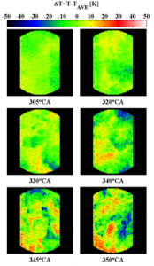
In the next stage of research, Dec and Hwang developed a single-line PLIF diagnostic to obtain planar temperature-maps of the TS in order to observe the magnitude and distribution of the inhomogeneities throughout the compression and early-expansion strokes. Toluene excited by a quadrupled Nd:YAG laser (266 nm) was used as a temperature-sensitive fluorescent tracer in the air-fuel mixture. In order to keep the environment of the combustion chamber well controlled (i.e. to have a fully uniform fuel/tracer mixture in the cylinder and no tracer breakdown due to the onset of combustion), the engine was used in motored operation by replacing the air (79% nitrogen and 21% oxygen) with pure nitrogen to prevent autoignition. This also eliminated oxygen quenching of the toluene fluorescence. The results, given at different crank angles (CA), show that TS occurred progressively through the latter compression and early expansion strokes (Figure 2), so that by the time autoignition occurs near top dead center (TDC = 360° CA), a significant thermal distribution exists.
Fired Operation
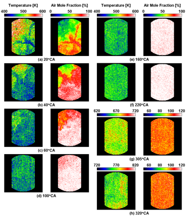
In fired operation, the key change in the system is the presence of residual combustion-product gases from previous cycles. Dec and Dronniou, in collaboration with visiting researcher Jordan Snyder, a Ph.D. student from Dr. Ron Hanson’s group at Stanford University, used a two-laser system to image the distribution and evolution of TS for this condition. With this two-line PLIF technique, lasers operating at 277 and 308 nm excited the fluorescence of 3-pentanone, another temperature sensitive tracer, in very close succession (a few microseconds), and two separate PLIF images were acquired. The 3-pentanone tracer was used because its fluorescence is not quenched by oxygen, unlike toluene, and thus can be used for experiments with the engine in fired operation. Further, 3-pentanone has a stronger signal at 277 and 308 nm. Having the two essentially simultaneous measurements allows both the temperature and species concentration to be determined. Applying this technique to a study of the residual mixing process provided simultaneous images of both temperature and air mole fraction during the intake and early compression strokes, allowing direct visualization of the mixing.

Figure 3 shows the results. The earliest images indicate a high amount of inhomogeneities in both temperature and air mole fraction, which was expected during this timeframe when the colder inducted air mixed with the hot residuals from the previous cycle. The two image types show good spatial correlation, with temperature inversely proportional to air mole fraction. The residual mixing process is roughly complete by a CA of 220°, where both the temperature and air mole-fraction distributions are homogeneous. TS development can be seen in the 305° and 320° CA temperature maps; however the air mole fraction images at these CAs remain homogeneous. These results imply that residual mixing is complete early in the compression stroke and is thus not a likely source of TS near TDC when autoignition and combustion occur, for low-residual engines like one used for this study. Therefore, given that the mixture is homogeneous after a CA of 220°, single-line PLIF measurements can be made with the engine in fired operation without concern of error due to inhomogeneities in the air-fuel mixture.
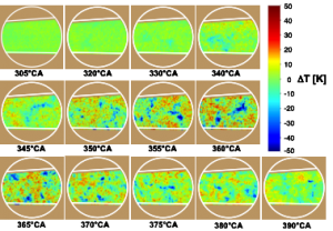
The team conducted these single-line measurements during the compression stroke under the same conditions studied in the two-line experiments (Figure 4). The results show that when wall temperatures were similar, the development of TS up to the point of autoignition is quite similar for either motored or fired operation, indicating the dominance of wall heat transfer and convection in forming the TS.
The work described here for the engine in fired operation was published by SAE International in 2011, and authors were recently awarded the 2011 SAE Arch T. Colwell Merit Award for this work.
Work on this project was a well-matched collaboration between Sandia National Laboratories and Stanford University, says Dec. “We have a great deal of knowledge in engine combustion and laser diagnostics, but we needed a different tool to fully investigate TS in the HCCI engine. Ron Hanson had the right solution, which allowed his student, Snyder, to gain some real-world experience.” The development of diagnostics for use in harsh engine environments is a necessary step for future HCCI engine development.
This work was supported by the US Department of Energy, Vehicle Technologies Program under Gurpreet Singh.